The SPPDG electronics research and development laboratory is a diverse facility with state of the art assembly, test and evaluation capabilities.
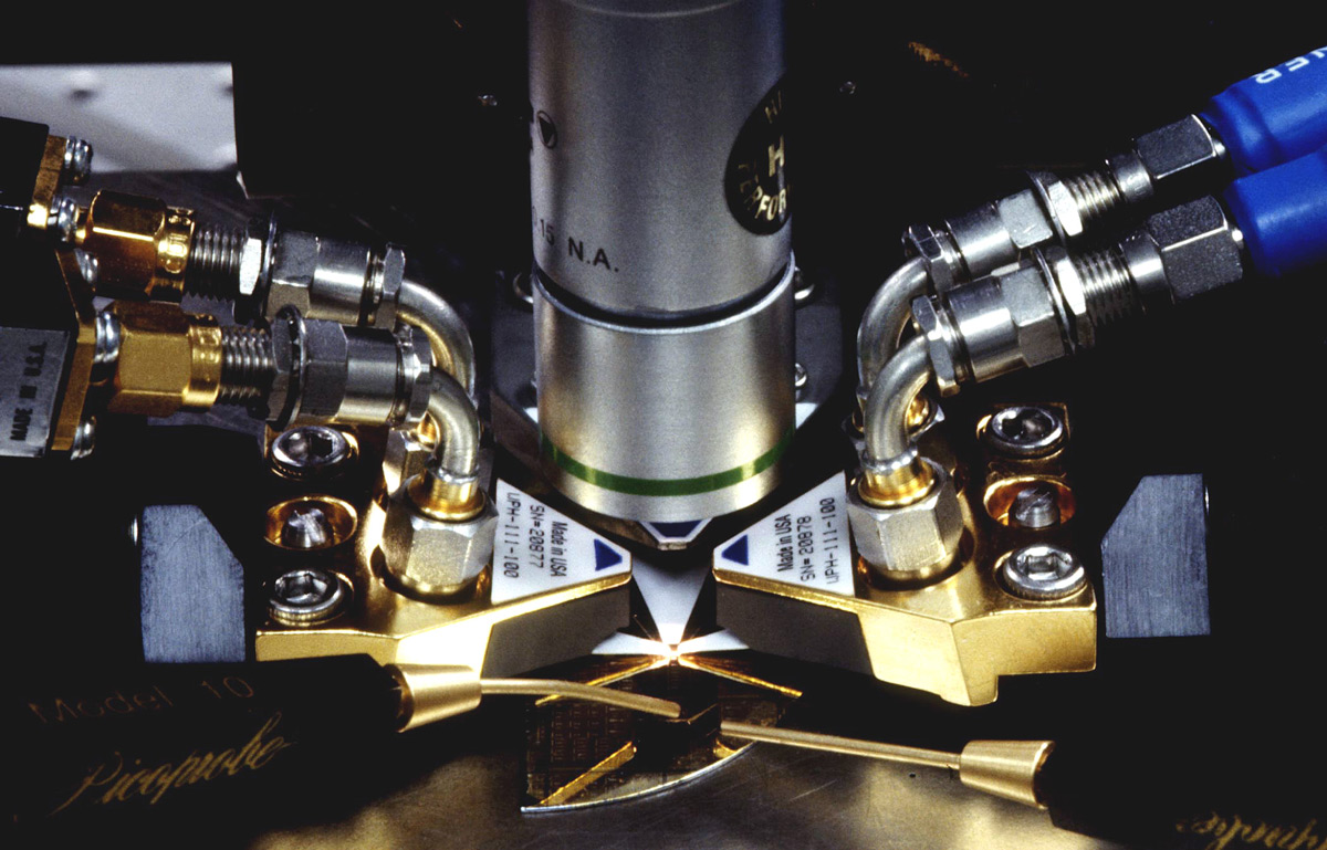
With a concentration on both high clock rate digital circuits and systems, analog radio frequency (RF) integrated circuits (ICs), and mixed signal integrated circuits and systems, the capabilities are in place to characterize materials, discreae passive and active components; digital, analog, and mixed-signal ICs, interposer structures, multichip modules (MCMs), fine-pitch printed circuit boards (PCBs), and complete prototype digital and mixed-signal processor systems. We have also been working for more than fifteen years to strengthen our capability to evaluate optical components and subsystems as well. The following photo (Fig.1) depicts an example of the type of analog test suite that we can assemble from our pool of laboratory equipment to test analog systems or integrated circuits that are under development by our team.
Fig.1 Microwave linearity measurements are typical of test lab bench configurations.
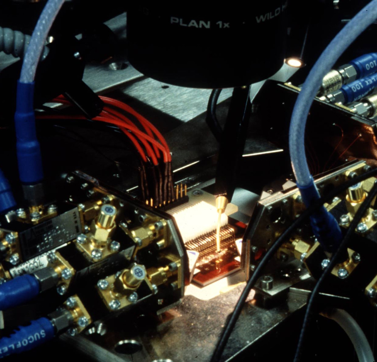
The following photo (Fig.2) depicts an example of the type of digital test suite that we can assemble from our pool of equipment to test digital systems or integrated circuits that are under development by our team. This particular equipment suite was assembled to test 80 gigabit/second multiplexer and demultiplexer integrated circuits designed by SPPDG engineers. Our ability to assemble these test suites very rapidly is enabled by our substantial equipment inventory, and the fact that all laboratory benches are both movable and reconfigurable with very little effort.
Fig.2 Photograph of complete test setup for 80 Gbps integrated circuit testing.
This capability exists to characterize signal interconnects of many different types, including transmission lines on multichip modules or printed circuit boards, integrated circuit connections, and any type of connections to or from a device. Numerous unique materials have been characterized, along with many types of discrete and embedded integral passive electrical components. These investigations are performed with a broad range of test instrumentation, with each instrument listed in order of increasing frequency capability.
This category of testing requires equipment that is capable of generating signals to be applied to the device under test (DUT), and acquiring output signals from the DUT. Our test equipment for these tasks includes a full range of measurement capabilities, ranging from DC up to 220 GHz frequencies, including bit error rate testing (BERT) up to 40 GHz; and a network analysis capability up to 220 GHz.
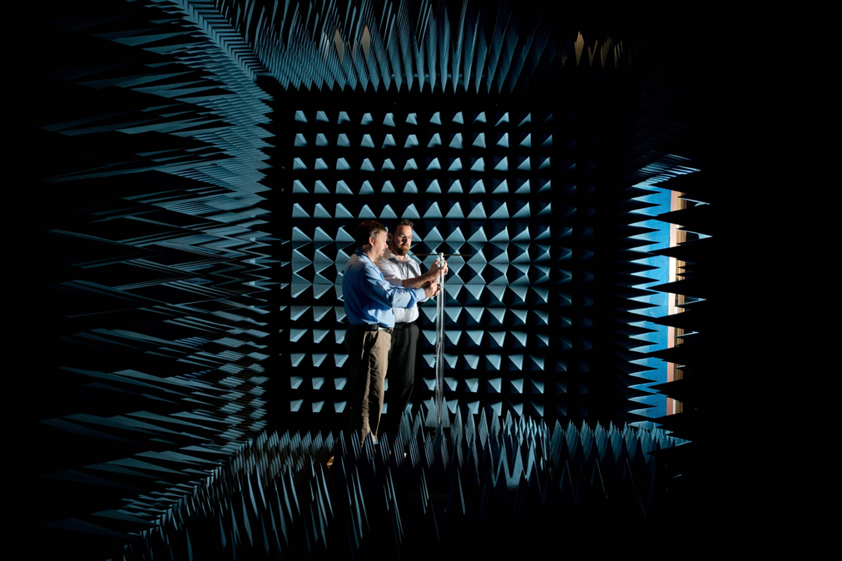
Highlights of the hundreds of items of test equipment in our laboratory include:The SPPDG laboratory includes at 12 x 12 x 24 foot ETS Lindgren anechoic chamber, capable of testing radio frequency systems from 700 MHz to 40 GHz. The room is lined with radiation-absorbing material, and test devices are placed on a rotating platform for measurement by the horn antenna (Fig.3) at the far end of the chamber. This facility has been used to characterize prototype antennas and analyze emissions from electronic components and systems.
Fig.3 Radio frequency anechoic chamber used for testing various types of antennas, transmitters, and receivers. Chamber is 12’ x 12’ x 24’ in dimensions, and was designed to function in the “far field” over a frequency range of approximately 700 MHz to 40 GHz, though it can be used at slightly higher and slightly lower frequencies with a small degree of nonideality.
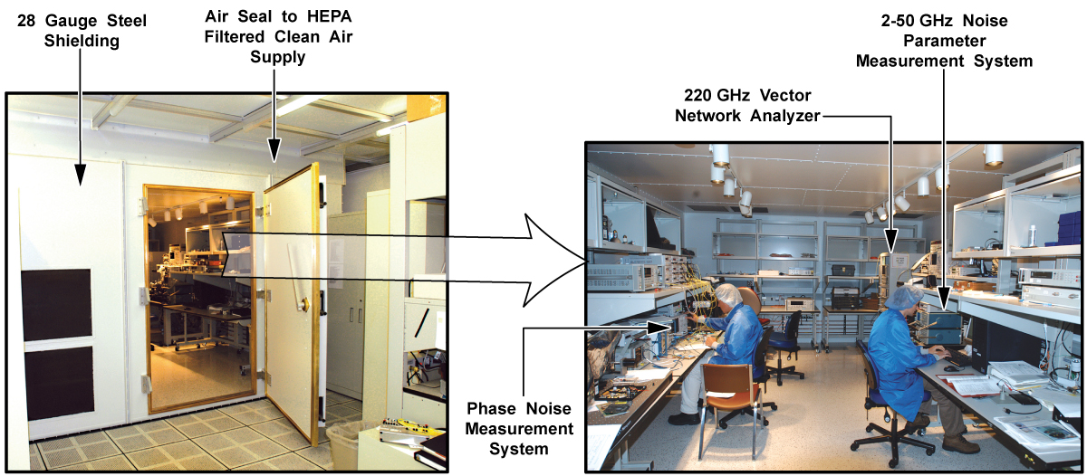
Mayo also has an ETS Lindgren Series 81 shield room (Fig.4) used to attenuate external radio frequency interference, allowing sensitive noise measurements. The room is 15 x 22 x 8 foot, and has been measured at greater than 100 dB attenuation from 1 kHz to 10 GHz.
Fig.4 ETS Lindgren Series 81 shield room providing 330 sq ft of “RF Quiet” testing floor space. Room provides >100 dB attenuation of external RF radio frequency interference. Poseidon noise measurement system, Agilent Vector Network Analyzer with Oleson mixers for 220 GHz vector network testing and Focus Microwaves Model 5002 Noise Parameter Measurement system.
Information updated Wednesday, November 17, 2021
Any use of this site constitutes your agreement to the Terms and Conditions and Privacy Policy linked below.
"Mayo," "Mayo Clinic," "MayoClinic.org," "Mayo Clinic Healthy Living," and the triple-shield Mayo Clinic logo are trademarks of Mayo Foundation for Medical Education and Research.